The American Meteor Society, Ltd. (AMS)
Radiometeor Project
by James Richardson
American Meteor Society
Radiometeor Project Coordinator
ABSTRACT: The basic concepts of meteor radio scatter and its uses are introduced, followed by a brief history of the American Meteor Society (AMS) Radiometeor Project. A detailed description is given of the Poplar Springs 55.26 MHZ radiometeor receiving system, along with its associated computer automated data collection system. The system specifications and examples of the graphical output are also included.
Reprinted with permission from "Radio Astronomy," the journal of the Society of Amateur Radio Astronomers (SARA), Nov/Dec, 1997.
Table of Contents
I. Introduction All sky watchers are familiar with the fleeting spark of a meteor against the night sky, marking the extinction of a small particle of the solar system. Few observers, however, realize that with the same brief flash, a myriad of man-made radio transmissions also bounced off the meteor, some signals traveling nearly halfway across the continent. These signals did not bounce off the tiny meteoroid itself, but instead reflected from the trail created by the meteoroid as it plowed through the mesopause region of the atmosphere. Whenever a meteoroid passes through the upper atmosphere it creates a column (actually an elongated paraboloid) of ionized air and free electrons behind it, usually less than 1 meter in diameter and tens of kilometers (km) long. Occurring at an atmospheric height of about 85 to 105 km (50 to 65 miles), the free electrons in this ionized trail are capable of reflecting radio waves from transmitters below on the Earth's surface (Davies, 1965). This type of reflection behaves very similar to light reflecting from a mirror, and is called a specular reflection. Meteor trail reflections are brief, however. As the trail rapidly diffuses into the surrounding air, it quickly looses its ability to reflect radio waves, causing most reflections to last less than 1 second. Infrequently, a large, bright meteor may create a trail capable of reflecting radio waves for up to several minutes. Meteor radio wave reflections are also called meteor echoes or events. If the radio waves from the transmitter below strike the meteor trail at a perpendicular, or right angle, then the reflected signal will be directed back towards the transmitter itself. This is called back-scatter, and a station set up to receive such signals is called a meteor radar. Back-scatter is one of the most common methods by which professional astronomers study meteors using radio waves. These reflections can be used to study the meteors which caused them because each meteor will generate a unique signal based upon its mass, velocity, inclination angle, direction of entry into the atmosphere, and distance from the transmitter. Meteor research of this type reached its height during the 1950's and 1960's at such facilities as those at Ottawa, Canada, and Jodrell Banks, England (McKinley, 1961). Current research of this type is being conducted using the powerful Arecibo Radio Telescope, located in Puerto Rico, to study extremely small micrometeors (Mathews, Meisel, Hunter, Getman, and Zhou, 1997). If the radio wave from the transmitter strikes the meteor trail at some incident angle other than perpendicular, then the reflected signal will be projected to some point on the ground some distance away from the transmitter. This is called forward-scatter, and the area on the ground where the signal has been reflected is called a forward-scatter footprint. This footprint will only be a few km wide and several km long (McKinley, 1961). Meteor trails can reflect radio signals over distances of up to 2000 km (1250 miles) between a transmitter and receiver. Most forward-scatter systems, however, operate at a distance of about 300 km to 1500 km (180 to 930 miles) (schanker, 1990). The forward-scatter of radio waves by meteor trails can serve two important purposes: First, the trails can be used to send brief encoded messages to distant receiver sites. This is called meteor burst communications, and is frequently used as a backup means to satellite communications. In North America, the most widely known meteor burst communications system is the SNOTEL system, used by The U.S. Natural Resources Water and Climate Center, located in Portland, Oregon, to monitor rain and snowfall levels at remote stations throughout the Rocky Mountains. These stations are fully automated weather stations and meteor burst transceivers, which relay their information to a master station upon command (schanker, 1990). In addition, amateur radio enthusiasts operating in the VHF bands also make frequent use of meteor scatter (MS), especially during major meteor showers (Owen, 1986). The second purpose for forward-scatter is the study of meteors, and is similar to that performed by the back-scatter systems. The advantage of this method is that transmitters broadcasting for purposes other than meteor radio scatter can be utilized, thus allowing the construction of a receiving station only by the researcher. The disadvantage of this research method is that the geometry is much more complex than in the back-scatter condition, making meteor parameters more difficult to determine (McKinley, 1961). Through the use of distant commercial radio transmitters, many amateur astronomers have also successfully establish forward-scatter receiving stations of their own. While most of these amateur stations are for the purpose of enjoyment only, a handful of stations have been designed for the purpose of collecting meteor data usable by the professional astronomical community. For nearly forty years, the American Meteor Society (AMS) has encouraged its amateur members to experiment with the establishment of forward scatter receiver systems. First successes in this area were had by Walter Scott Houston, of the AMS Kansas Meteor Group, in the late 1950's. The Kansas system utilized an automatic electronic circuit to count meteor echoes from a professionally operated transmitter at Cedar Rapids, Iowa (Houston, 1958). This system remained in operation until 1961. In the late 1970's, the advent of the personal computer made it possible for serious amateurs to create even more sophisticated systems for the detection and recording of radiometeor data. In order to germinate this potential within the amateur community, Dr. David D. Meisel (State University of New York at Geneseo) created the AMS Radio Scatter Program in 1977, which is now called the AMS Radiometeor Project (Meisel, 1977; Meisel & Richardson, 1997)). As a professional-amateur collaboration, the purpose of this project is to establish a network of amateur operated forward-scatter receiving stations. The data collected from these stations will then be used in the research conducted by AMS affiliated professional astronomers. Many amateur experiments were conducted throughout the 1980's within this program. Notable successes were achieved by such amateurs as William Black (1983), who demonstrated the ability to conduct back-scatter meteor observations utilizing airport Instrument Landing System (ILS) beacons; Kenneth Pilon (1984), who became the first amateur to use a microcomputer for detecting and recording meteor events; Michael Own (1986), who recorded the 1985 Giacobinid (October Draconid) outburst using Television video carrier signals; and Meteor Group Hawaii (MGH), led by Michael Morrow and George Pokarney, who developed portable systems for both HF and VHF meteor work (Meisel, 1987). Building upon these earlier successes, the author has established a working prototype station for the AMS, located in the rural countryside of northwestern Florida, in the small community of Poplar Springs (Richardson, 1993). II. Poplar Springs Radiometeor Station The Poplar Springs Radiometeor Station is an amateur built and operated system used for monitoring the meteor flux through forward-scatter radio techniques, and is designed to collect data for professional scientific analysis. Established in March of 1993, The system was the first station to begin full-time operation in the AMS Radiometeor Project. The AMS has also utilized this station as a prototype system, successfully carrying over the configuration and techniques developed at Poplar Springs to other network stations. These stations are designed to collect data on the radiometeor flux on a continuous, 24-hour per day basis. At its most basic level, the station consists of two parts: a Radio Receiver system, and a Computer Automated Data Collection system. The following sections describe the station in further detail. Section III discusses the Radio Receiver system, the primary component of which is a radiometeor receiver setup to monitor meteor echoes from distant channel 2 television transmitters. In addition, the receiver system also includes a noise receiver, and computer coupling devices. Section IV discusses the Computer Automated Data Collection system, which uses an Apple IIe computer programmed to monitor the output from the radio system, detect meteor events, and store data on each event to floppy disk. Finally, Section V describes the computer screen display and the simple data reduction programs provided to the system operator. III. Radio Receiver System The Radio Receiver system for the station contains two separate sub-systems, a radiometeor receiver and a broad-band noise receiver. The radiometeor receiver configuration is fairly typical of similar amateur systems, consisting of an outdoor antenna, filters, pre-amplifier, frequency converter, and a standard shortwave receiver. A block diagram of the system is shown in Figure 1. The antenna is a 5-element, horizontally polarized yagi antenna, mounted at 2 wavelengths above ground and 0o tilt attitude. Notch filters are employed in the signal path to block interference from nearby television and FM commercial transmitters, while a high-pass filter blocks image frequency interference from the shortwave band. A pre-amplifier and frequency converter then boost the overall signal level, and then reduce the frequency to within the range of the shortwave receiver (<30 MHz). The home-built converter's local oscillator functions at 29.995 MHz, reducing the input frequency of 55.260 MHz to 25.265 MHz, which is purposefully below the frequencies for Citizens Band (CB) and 10-meter Amateur Radio Band transmissions. The receiver is a digitally controlled Sangean ATS-803A Shortwave Receiver operating in the Continuous Wave (CW) mode within a 6 kHz bandwidth around the central frequency. The Power Level meter circuit within the receiver is tapped for output to the computer system, while a speaker or headphone output permits the operator to audibly monitor the receipt of meteor echoes by the system. Figure 1: Block diagram of the Poplar Springs Radiometeor Station, showing
the radiometeor receiving system, noise monitoring system, and computer data
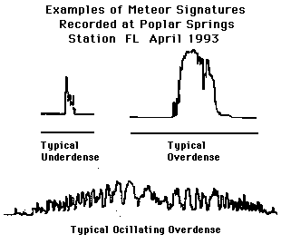
aquisition system. The radiometeor receiver utilizes distant television Channel 2 transmitters as the forward-scatter signal source, at a frequency of 55.26 MHz. This is the plus (+) offset frequency for the Channel 2 picture (or video) carrier signal. The receiver mode is set to monitor the continuous wave (CW) signal of the video carrier itself, without regard to the actual modulated intelligence (or picture). Meteor echoes and/or very weak tropospheric scatter signals are received from four primary transmitters, as listed in Appendix 1. These transmitters are located in northern Mississippi, South Carolina, Tennessee, and Maryland, in order of distance from the receiver. An antenna bearing azimuth of 45o has been chosen to maximize the receipt of meteor echoes originating from the three most distant stations, and to suppress the tropospheric scatter signal from the closest (Mississippi) station as much as possible. The resulting configuration yields activity from three forward-scatter "links" within the beamwidth: (1) the northwestern "hot spot" of the Florida-South Carolina link, (2) the southeastern hot spot of the Florida-Tennessee link, and (3) both hot spots for the more distant Florida-Maryland link. This setup yields about 2000 to 3000 detected events per day during the annual peak of overall meteor activity in July-August. Following the annual activity variation, this rate dips down to about 300 to 600 events per day in February-March. The receiver system also shows a typical daily variation in sporadic meteor activity, with a peak at about 8 a.m. local time, and a trough at about 8 p.m. local time. Audibly, the short "pings" of underdense trails, the longer "bongs" of overdense trails, and Doppler shifted "whoops" or "whistles" of meteor head echoes can be easily detected by ear (see Figure 2). Figure 2: Examples of "typical" radiometeor types monitored by the station
which fall into three primary catagories: (1) Underdense (U) events, (2) Overdense
(O) events, and (3) Oscillating Overdense events. Not shown are the Transition (T)
events, which form a transition region between the Underdense and Overdense
types. In addition to the radiometeor receiver, a separate noise receiver is employed to facilitate the cancellation of electrostatic noise spikes by the system. This portion of the system uses a less expensive analog shortwave receiver with an indoor antenna, operating at about 2.5 MHz. The audio output of the noise receiver is then tapped for output to the computer system. Because the noise receiver is used only to detect broad-band Radio Frequency Interference (RFI), this receiver does not require the high sensitivity and calibrated output of the radiometeor receiver. In order to transfer the desired radio outputs to the computer, the system utilizes two home-built opto-coupler devices. These devices transform by optical coupling the variable voltage levels tapped at the radiometeor and noise receivers into two variable resistance signals which can be read by the Game I/O port at the back of the computer. The Game I/O port feature of the computer then transforms each resistance into a variable 8-bit digital signal with a range of 0 to 255 digital units. The data collection software monitors and stores its collected information in these digital units (Richardson, 1996). Conversion of data back to antenna dBm or microvolt values occurs at the data analysis level, utilizing additional data collected from periodic system calibration tests (Meisel & Richardson, 1997). IV. Computer Automated Data Collection System The Computer Automated Data Collection system utilizes an enhanced Apple IIe personal computer as the hardware platform. A software package was written specifically for this purpose and performs the following: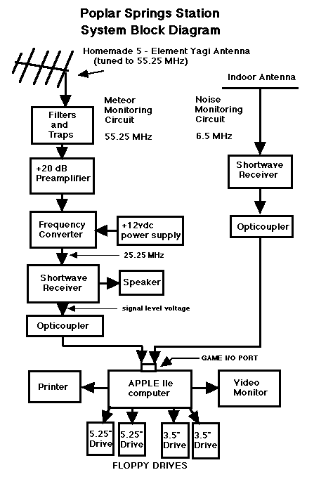
The use of two floppy disk drives permits the swap over of data collection from one drive to the other whenever a disk becomes full. Figure 1 shows the present configuration of this system using two 3.5 inch disk drives for data collection with two 5.25 drives used for computer boot-up and software loading.
The computer automated detection method currently being used by the software employs a floating, selective threshold crossover detection method. Briefly stated, the computer software monitors the output from the radiometeor receiver, looking for the sudden, rapid signal rise indicative of a meteor event. The software contains the following parameters:
(1) All detected events must rise greater than a preselected threshold value above the receiver background noise level. If, for whatever reason, the receiver background level floats above the low "peg" for the system, the event threshold will float along with it. The threshold value is chosen by the user when the software is started, and is selected to optimize a particular system's performance.
(2) Long duration events (greater than 2 minutes) are discarded by the system. Meteor events of this duration are very infrequent, while other propagation modes, such as high aircraft (for short range systems), sporadic E, and D-layer scatter can all generate similar long duration events.
(3) Oscillating events with periods of less than 3 seconds are generally detected only once. Because of the high variability present in oscillating events, further development will be necessary to perfect this feature.
(4) Radio frequency interference (RFI), including lightning events, are ignored by the system through the use of a second receiver to detect such events. When the computer detects an event occurring on both receivers simultaneously, the event is ignored.
(5) Further event discrimination occurs during the statistical analysis of the collected data at the Physics/ Astronomy Department of the State University of New York at Geneseo. All questionable events are discarded.
The software stores three basic parameters on each detected event: beginning date and time of event occurrence (epoch), maximum signal strength achieved by the event (peak power), and event duration. These three simple parameters can yield a surprising amount of information about the source meteor. Times collected by the system come from an internal computer clock, with 1/100 second accuracy. Recent improvements to the system have raised the sample rate of the software from 5 samples per second up to 15 samples per second. This gives the data collection system a time resolution of 0.07 seconds, with a minimum detectable event duration of 0.09 seconds. These system parameters are also summarized in Appendix 1. After each detected event, an approximate 2-4 second period of "dead time" occurs in the data sampling stream while disk storage takes place. While undesirable in high count situations, this dead time is unavoidable using the current platform.
V. Computer Display and Simple Data Reduction
In addition to data collection and storage, the software also provides the system operator with a strip-chart display of the radiometeor receiver output. The parameters collected on the last detected meteor event, along with "housekeeping" parameters are also displayed. Figure 3 shows the display for the 'data collection mode' for the computer. This display shows a moving-point 'strip chart' type display of signal amplitude (0-255 units) over time (0-260 samples: 58 seconds). These screen dumps were made while the old sample rate was still in place. The upper part of the figure shows underdense meteor events, and the bottom part is a sample of overdense meteor events detected by the system. The bottom of each screen displays text data about the event last detected by the computer, using the following abbreviations:
1. DATE - shows the name of the disk file to which data is being stored.
2. ST - Start time of event (UTC), to 1/100 seconds.
3. ET - End time of event (UTC), to 1/100 seconds.
4. SS - Signal strength (maximum), 0-255 units.
5. DR - Signal duration, in seconds.
6. WT - Wait time in seconds. Amount of time between this event and last detected event.
7. NF - Noise flag status; 0 = no noise, 1 = noise detected.
8. D# - Disk drive number in use.
9. R# - Event record number in current file, also total number of events for the day up to that time.
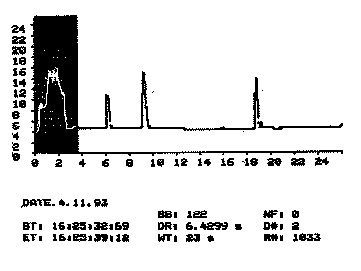
Figure 3: Sample screen dump of the computer display for the system, showing three short underdense events, followed by a longer overdense event (shown on left - inverse color). The numerical display shows the data collected on this last overdense event.
While the system is designed to collect meteoric data for detailed off-line statistical analysis, a few simple data reduction programs are provided to permit the operator to monitor the performance of the station. A sample graph produced by these programs is shown in Figure 4, displaying actual collected data. The graph shows the diurnal histogram of hourly rates for March 16, 1993, using a standard bar graph format. Note the minimum in meteor activity around 000-0300 UTC (local 6-9 pm), with the maximum in meteor activity occurring around 1200-1500 UTC (local 6-9 am).
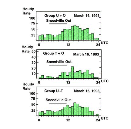
Figure 4: Diurnal histogram of event hourly rates for March 16, 1993. The upper graph shows the cumulative numbers, with the graphs for the Overdense + Transition (O+T) group and the Underdense - Transition (U-T) group shown below. Note the sinusoidal behavior of the graphs, due to the rotation of the Earth in the sporadic meteor flux (which reaches a peak near dawn, and a minimum near sunset.
VI. Conclusion As a prototype station, the Poplar Springs Radiometeor Station has remained in nearly continuous operation since March, 1993. Hardware and software improvements have occasionally been made to enhance system performance and reliability. In 1996, a second station utilizing this configuration was established by James Riggs in West Point, California. Other stations are currently under development. Using the lessons learned from the prototype, the AMS is also making plans for a "next generation" station utilizing an upgraded hardware and software platform. By the end of 1995, over one million individual meteor events had been logged by the Poplar Springs Station, which are currently undergoing detailed statistical analysis. Early scientific results from the project have also been recently presented at the 190th American Astronomical Society (AAS) convention (Richardson & Meisel, 1997). While there is always room for continued system improvement, the Poplar Springs Radiometeor Station has successfully demonstrated the ability of an amateur designed, constructed, and operated system to collect scientifically valid data on the long-term meteor flux.
Questions or comments regarding this paper or the AMS Radiometeor Project should be directed to:
James Richardson
APPENDIX 1: System Specifications AMS Radiometeor Project Poplar Springs Station Operator: James E. Richardson, Jr. Receiver Site: Poplar Springs township, Holmes County, FL, USA Lat: 30o 55' 57" North Long: 85o 35' 41" West Altitude: 185 ft. (56.4 meters) Antenna: Height = 11 meters (2.0 wavelengths), 5 element, horizontally polarized yagi, 10 dB gain, aimed at 45o east of North, with a 0 o tilt attitude. Receiver Sensitivity: -112 dBm (0.56 uv) to -96 dBm (3.55 uv) at 50 ohm, in a 6 kHz bandwidth. Computer Resolution: 8-bit signal input at 15 samples per second, 0.07 sec. time resolution, 0.09 sec. minimum event. Received Signal: Television channel 2 video carrier signal at 55.26 MHz (+ offset). All transmitter powers at 100 kilowatts, continuous broadcast (except Sneedville, which operates 0730-2400 EST/EDT). Transmitter Lat.(o) Long.(o) Dis.(km) Az./Offset(o) Charleston, SC 32.7 80.0 564 68 / +23 Sneedville, TN 37.0 83.2 710 18 / -27 Baltimore, MD 39.3 76.8 1230 38 / -7 Ms. State, MS 33.5 88.3 382 318 / -87 * *NOTE: Side lobe reception assumed to be some 40 dB down from other signals. No evidence of reflections from this station has shown up clearly in the data. Approximate Radiant Sensitivity: Southern Radiants: 68o to 230o with Max alt. 43o at 149o Az. Northern Radiants: 215o to 26o with Max alt. 26o at 300o Az. Approximate Meteor Sensitivity: Underdense: magnitude; 3.5m to 5.5m velocities; 22 to 50 km/sec Overdense: magnitudes; -1m to 3m velocities; 12 to 60 km/sec (Predictions based on classical meteor theory using a custom MathCad template.) References Black, W.H., (1983, July). "Observing Meteors by Radio," Sky & Telescope, pp.61-62. Davies, K., (1965). Ionospheric Radio Propagation. NBS Monograph 80. (Reprinted by Dover Pub., 180 Varick St.) Houston, W.S, (1958, July). "The Amateur Scientist: Counting Meteors by Radio," Scientific American, pp 108-111. Mathews, J.D., Meisel, D.D., Hunter, K.P., Getman, V.S., & Zhou, Q. (1997, March). "Very High Resolution Studies of Micrometeors Using the Arecibo 430 MHz Radar," Icarus. McKinley, D.W.R., (1961). Meteor Science and Engineering. MacGraw-Hill Book Co.: New York. Meisel, D.D., (1977, January). The AMS Radio Scatter program, AMS Bulletin 203. The American Meteor Society, State University of New York At Geneseo. Meisel, D.D., (1987). "New Approaches to Some Methodological Problems of Meteor Science." presented at the First GLOMET Symposium, August 1985, Dushanbe, Takijistan, pp.389 - 404. in Middle Atmosphere Program, Handbook 25, (ed. R.G. Roper), published by ICSU SCOSTEP. Meisel, D.D. & Richardson, J.E., (1997, January). The AMS Radiometeor Project, AMS Bulletin 203 (revised). The American Meteor Society, State University of New York At Geneseo. Meisel, D.D., Richardson, J.E., & Mallama, A. (1997, Summer). "Wavelet and Fourier Analysis of Meteor Rate Data." Oral presentation by DDM to the American Astronomical Society (BAAS-33.01). Owen, Michael. (1986, June). "VHF Meteor Scatter, an Astronomical Perspective," QST, pp. 14-20. Pilon, K., (1984, May). "Computer Adventures: Meteor astronomy at home," Popular Science, p. 80. Richardson, J.E., (1993, Fall). "The Poplar Springs Meteor Patrol: A General Description," Meteor News, No. 105. Richardson, J.E., (1996, December). Apple IIe Meteor Burst Software Users Manual, Version 4.0. The American Meteor Society, State University of New York at Geneseo. Richardson J.E. & Meisel, D.D. (1997, Summer). "An Amateur Radiometeor Network and its Scientific Results." Oral presentation by JER to the American Astronomical Society (BAAS-33.02). Schanker, J.Z., (1990). Meteor Burst Communications. Norwood, MA: Artech House.
Last updated: April 13, 2000 at 1500 UTC
AMS Radiometeor Project Coordinator
Lunar and Planetary Laboratory
University of Arizona
Tucson, AZ 85721
USA
E-mail: richardson@amsmeteors.org
© 2000 American Meteor Society, Ltd.